Wednesday, September 22, 2010

Adder

Half adder:

A half adder is a logical circuit that performs an addition operation on two one-bit binary numbers often written as A and B. The half adder output is a sum of the two inputs usually represented with the signals Cout and S where sum=2*Cout+S. Following is the logic table for a half adder:

Inputs

Outputs

A

B

C

S

0

0

0

0

0

1

0

1

1

0

0

1

1

1

1

0


Example half adder circuit diagram

As an example, a Half Adder can be built with an XOR gate and an AND gate.

              ___________
     A ------|           |
             |   Half    |----- S=A(+)B
             |   Adder   |
             |           |----- C=A.B
     B ------|___________|

Full adder:
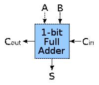
Schematic symbol for a 1-bit full adder with Cin and Cout drawn on sides of block to emphasize their use in a multi-bit adder.

A full adder is a logical circuit that performs an addition operation on three one-bit binary numbers often written as A, B, and Cin. The full adder produces a two-bit output sum typically represented with the signals Cout and S where sum=2*Cout+S. The full adder's truth table is:

Inputs

Outputs

A

B

Ci

Co

S

0

0

0

0

0

1

0

0

0

1

0

1

0

0

1

1

1

0

1

0

0

0

1

0

1

1

0

1

1

0

0

1

1

1

0

1

1

1

1

1

A full adder can be implemented in many different ways such as with a custom transistor-level circuit or composed of other gates. One example implementation is with S=(A(+)B)(+)Cin and Cout=(A.B)+(Cin.(A(+)B)).

Example full adder circuit diagram
Inputs: {A, B, Cin} → Outputs: {S, Cout}

Example full adder circuit diagram using only NAND and XOR gates
Inputs: {A, B, Cin} → Outputs: {S, Cout}

In this implementation, the final OR gate before the carry-out output may be replaced by an XOR gate without altering the resulting logic. Using only two types of gates is convenient if the circuit is being implemented using simple IC chips which contain only one gate type per chip.

A full adder can be constructed from two half adders by connecting A and B to the input of one half adder, connecting the sum from that to an input to the second adder, connecting Ci to the other input and OR the two carry outputs. Equivalently, S could be made the three-bit XOR of A, B, and Ci, and Co could be made the three-bit majority function of A, B, and Ci.

Tuesday, September 21, 2010

Digital IC Terminology

Current and voltage Parameters:

· VIH(min)-High Level Input Voltage: The minimum voltage level required for a logical 1 at an input. Any voltage below this level will not be accepted as a HIGH by the logic circuit.

· VIL(max)-Low Level Input Voltage: The maximum voltage level required for a logical 0 at an input. Any voltage above this level will not be accepted as a LOW by the logic circuit.

· VOH(min)-High Level Output Voltage: The minimum voltage level at a logic circuit output in the logical 1 state under defined load conditions.

· VOL(max)-Low Level Output Voltage: The maximum voltage level at a logic circuit output in the logical 0 state under defined load conditions.

· IIH(min)-High Level Input Current: The current that flows into an input when a specified high level voltage is applied to that input.

· IIL(max)-Low Level Input Current: The current that flows into an input when a specified low level voltage is applied to that input.

· IOH(min)-High Level Output Current: The current that flows from an output in the logical 1 state under specified load conditions.

· IOL(max)-Low Level Output Current: The current that flows from an output in the logical 0 state under specified load conditions.

The high state noise margin VNH is defined as

VNH=VIH(min)-VOH(min)

The low state noise margin VNL is defined as

VNL=VIL(max)-VOL(max)

Carry Propagation

The addition of two binary numbers in parallel implies that all the bits of the angend and addend are available for computation at the same time.

As in any combinational ckt, the signal must propagate through the gates before the correct output sum is available in the output terminals.

A binary parallel adder is a digital function that produces the arithmetic sum of two binary numbers in parallel. It consists of full adders connected in cascade, with the output carry from one full adder connected to the input carry of the next full adder.

Figure shows the interconnection of 4 full adder (FA) ckts to provide a 4 - bit binary parallel adder. The augend bits of A and the addend bits of B are designated by subscript numbers from right to left, with subscript 1 denoting the low order bit. The carries are connected in a chain through the full adders. The input carry to the adder is C1 and the output carry is C5. The S outputs generate the required sum bits. When the 4 bit full adder ckt is enclosed within an IC package, it has four terminals for the augend bits, four terminals for the addend bits, four terminals for the sum bits, and two terminals for the input and output carries.

Binary Coded Decimal (BCD) Adder

Consider the arithmetic addition of two decimal digits in BCD together with a possible carry from a previous stage.

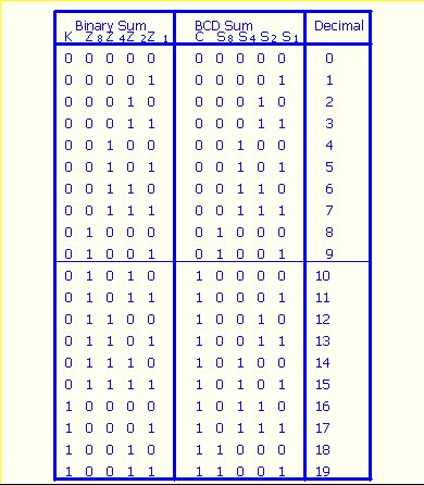
Each input digit does not exceed 9, the output sum cannot be greater than 9+9+1=19.

This adder will from the sum in binary and produce a result which may range from 0 to 19.

We found the derivation of a BCD adder, when the binary sum is equal to or less than 1001, the corresponding BCD number is identical.

When the binary sum is greater then 1001, the addition of binary 6(0110) to the binary sum converts it to the correct BCD representation and also produces an output carry as required.

An output carry can be expressed by the Boolean function: C=K+Z8Z4+Z8Z2: When C=1, it is necessary to add 0110 to the binary sum and provide an output carry for the next stage.

A decimal parallel adder that adds n decimal digits needs n BCD adder stages. The output carry one stage must be connected to the input carry of the next higher order stage.

Magnitude Comparator

A magnitude comparator is a combinational ckt that compares two numbers, A and B, and determines their relative magnitudes.

The outcomes of the comparison is specified by three binary variables that indicate whether A>B, A=B or A

Consider two numbers A and B, with four digits each A=A3A2A1A0 and B=B3B2B1B0

The equivalence function: xi=AiBi+A’iB’i as i=0,1,2,3,….

If (A=B)=x3x2x1x0

(A>B)=A3B’3+x3A2B’2+x3x2A1B’1+x3x2x1A0B’0

(A3B3+x3A’2B2+x3x2A’1B1+x3x2x1A’0B0

Decoder

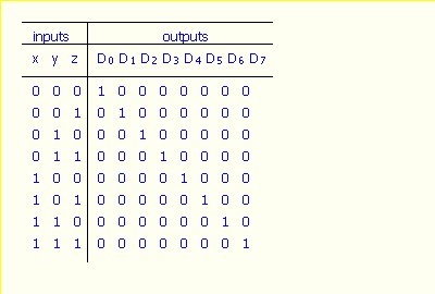
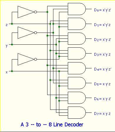
A decoder is a combinational ckt that converts binary information from n input lines to a maximum of 2n unique output lines.

If the n-bit decoded information has unused or don’t care combinations, the decoder output will have less than 2n outputs.